
For Chinese Version: Here; 中文: 这里
Transystem can turn the DXF model to ANSYS APDL. Though many software can realize this function, these software do not change the model to finite element model, they just turn the model to the geometric model. When we use such tools to transform the models, we need to mesh the model and assign your own section size. So I develop this simple software and leave a custom APDL txt file, when Transystem transforms the model in DXF file to ANSYS APDL, it will combine the custom txt file with the model and generate the perfect APDL command, what we need to do is to built the model in DXF file. This is very useful for huge model such as bridges and high-rise buildings.
Download
This tool is published in two types: exe and pyc. exe file could be executed in Windows(x64) system. But pyc file could run in Windows, MacOS and Linux system. pyc file is an executable file with python interpreter(v3.5), but it need another three packages: Numpy, Pandas and Dxfgrabber.
You can download the latest version from Transystem Change Log
Tutorial
Currently, this tool is just used for truss or frame system supports truss, frame and shell system. I plan to add more function to it. Before using this tool, we need to draw the model in CAD, different truss elements or beam elements should be specified to different layers. Please do not use the default 0 layer!
DXF转ANSYS APDL工具
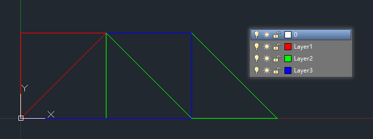
Here, I built the simple truss model in CAD and assigned three different layers to truss elements with different section size. To be obvious, I set different colors to the layers, but this is not necessary.
Then, we need to built a txt file. This file contained the custom APDL command used to add to the the finial command stream. The APDL command part in the file should be written with same indent and use same indent symbol (All Tab or All Space).
|
1 2 3 4 5 6 7 8 9 10 11 12 13 14 15 16 17 18 19 20 21 22 23 24 |
:Start: FINISH /CLEAR /PREP7 ET,1,LINK1 R,1,0.01 R,2,0.005 R,3,0.0125 MP,EX,1,2.1E11 MP,PRXY,1,0.3 :Layer1: TYPE,1 MAT,1 REAL,1 :Layer2: TYPE,1 MAT,1 REAL,2 :Layer3: TYPE,1 MAT,1 REAL,3 :End: FINISH |
In the txt file:
- :Start: Command after it will be add to the head of the finial APDL command, it could be used to specify the element type, real constant and material model;
- :End: Command after it will be add to the tail of the finial APDL command, it could be used to finish the /prep7 process and start to analyze the model;
- :LayerX: Name of the layer, the “:” cannot be ignored. the custom command after it will be add to the head of each layer with same name when each layer transforms to APDL command;
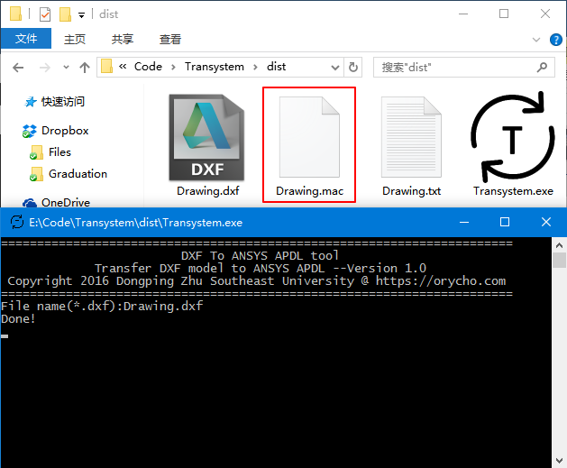
Save the DXF file and keep the name of the txt file with DXF file. Put them in the same folder with Transystem and open Transystem. Input the name of DXF file, the software will generate the mac file:
DXF转ANSYS APDL工具
This mac file is simple, it contain the APDL command of the whole model:
|
1 2 3 4 5 6 7 8 9 10 11 12 13 14 15 16 17 18 19 20 21 22 23 24 25 26 27 28 29 30 |
FINISH /CLEAR /PREP7 ET,1,LINK1 R,1,0.01 R,2,0.005 R,3,0.0125 MP,EX,1,2.1E11 MP,PRXY,1,0.3 TYPE,1 MAT,1 REAL,1 N,5,1.0,1.0,0.0,$N,6,0.0,0.0,0.0,$E,5,6 N,7,1.0,1.0,0.0,$N,8,1e-16,1.0,0.0,$E,7,8 N,9,1e-16,1.0,0.0,$N,10,0.0,0.0,0.0,$E,9,10 TYPE,1 MAT,1 REAL,2 N,3,1.0,0.0,0.0,$N,4,1.0,1.0,0.0,$E,3,4 N,17,1.0,1.0,0.0,$N,18,2.0,0.0,0.0,$E,17,18 N,19,2.0,0.0,0.0,$N,20,3.0,0.0,0.0,$E,19,20 N,21,3.0,0.0,0.0,$N,22,2.0,1.0,0.0,$E,21,22 TYPE,1 MAT,1 REAL,3 N,1,0.0,0.0,0.0,$N,2,1.0,0.0,0.0,$E,1,2 N,11,1.0,0.0,0.0,$N,12,2.0,0.0,0.0,$E,11,12 N,13,2.0,0.0,0.0,$N,14,2.0,1.0,0.0,$E,13,14 N,15,2.0,1.0,0.0,$N,16,1.0,1.0,0.0,$E,15,16 FINISH |
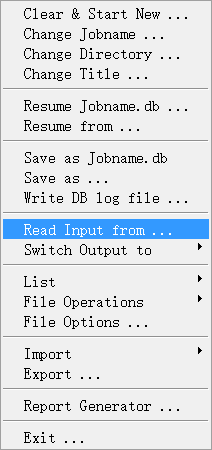
Open ANSYS,select Read Input from:
DXF转ANSYS APDL工具
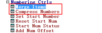
Model will be generated fluently, then we select Merge Item and Compress Numbers, you can also add these commands to :End: section in custom APDL txt file:
DXF转ANSYS APDL工具
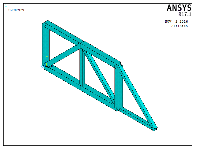
Here we can see the model generated by this software, it can be used to analyze quickly, you can also add the all analyzing commands in :End: section:
DXF转ANSYS APDL工具
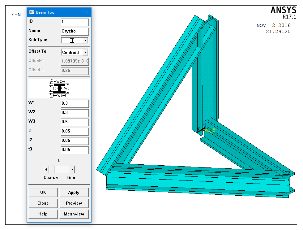
Transystem can also be used to deal with beam188, beam188 can be generated by two node. For beam188, default z axis of local coordinate system is parallel to z axis of global coordinate system. If the x axis of local coordinate system is parallel to z axis of global coordinate system, then the z axis of local coordinate system will point to the positive direction of x axis of global coordinate system. The following image shows the default section dection:
DXF转ANSYS APDL工具
Hence, Transystem can be used to generate beam model of structures, this is very useful to the bridge and frame model in civil engineering.

看看~~~